Case 08 / Aerodynamics & structures
NACA 0012 wing CFD and structural analysis
A NACA 0012 wing study that transfers CFD pressure loads into a structural model and compares stress, deflection and mass across nine structural variants.
CFD pressure loads · 9 structural variantsCFD modelling, pressure-load transfer and structural comparison
How does a computed airflow become a structural load, and what changes when the wing structure changes?
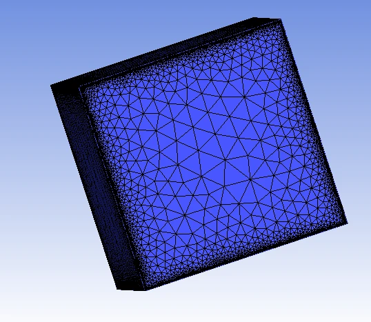
I connected an ICEM/Fluent wing-flow analysis to an ANSYS Static Structural model to study how aerodynamic pressure loads affect the wing. The figures show the original solver results; the interactive charts compare the report’s aerodynamic samples and structural variants.
Method and workflow
- 01
Build and mesh
Construct the NACA 0012 wing, surrounding flow domain and numerical mesh. Record geometry and boundary conditions.
- 02
Solve the flow
Study selected incidence and sideslip conditions with a pressure-based solver and realizable k–ε model.
- 03
Transfer pressure
Map the saved CFD pressure loading to the structural wing with its rib, spar and skin representation.
- 04
Compare responses
Inspect mass, stress, displacement and safety factor across the original structure and eight modifications.
Read the flow. Follow the load.
Six incidence conditions from the report appendix. Connecting lines are a visual guide; the sampling does not locate stall precisely.
Less mass changes the response.
Inspect the original structure and eight modifications. The chosen safety-factor threshold is a comparison aid, not a certification requirement.
| Report case | Mass / kg | Stress / MPa | Displacement / m | FoS | Selected threshold |
|---|---|---|---|---|---|
| 189.96 | 191.22 | 0.328 | 1.464 | Below | |
| 187.71 | 189.64 | 0.117 | 1.318 | Below | |
| 188.48 | 239.00 | 0.418 | 1.172 | Below | |
| 188.83 | 192.87 | 0.331 | 1.452 | Below | |
| 155.67 | 239.00 | 0.419 | 1.171 | Below | |
| 223.20 | 160.87 | 0.272 | 1.740 | Meets | |
| 226.24 | 153.34 | 0.255 | 1.826 | Meets | |
| 234.29 | 158.84 | 0.262 | 1.763 | Meets | |
| 202.94 | 177.70 | 0.299 | 1.576 | Meets |
Compare stress, mass, displacement and factor of safety separately. Large reported displacements require checking whether the structural model’s small-deformation assumptions still apply.
Project figures
Model assumptions and scope
- One-way CFD pressure transfer into a static structural model; dynamic aeroelasticity and flutter are outside the analysis.
- Six incidence samples describe the sampled aerodynamic response without locating stall precisely. Mesh convergence needs to be assessed for each result of interest.
- Contours and numerical comparisons use the project solver results. Displayed deformation is a simulated response.
Potential extensions
Check mesh convergence across representative conditions and verify that transferred pressure produces consistent resultant structural loads.
Let’s work through it.
Robotics, simulation and control consultation across Canada, with remote support available internationally. Share your system and the result you need.